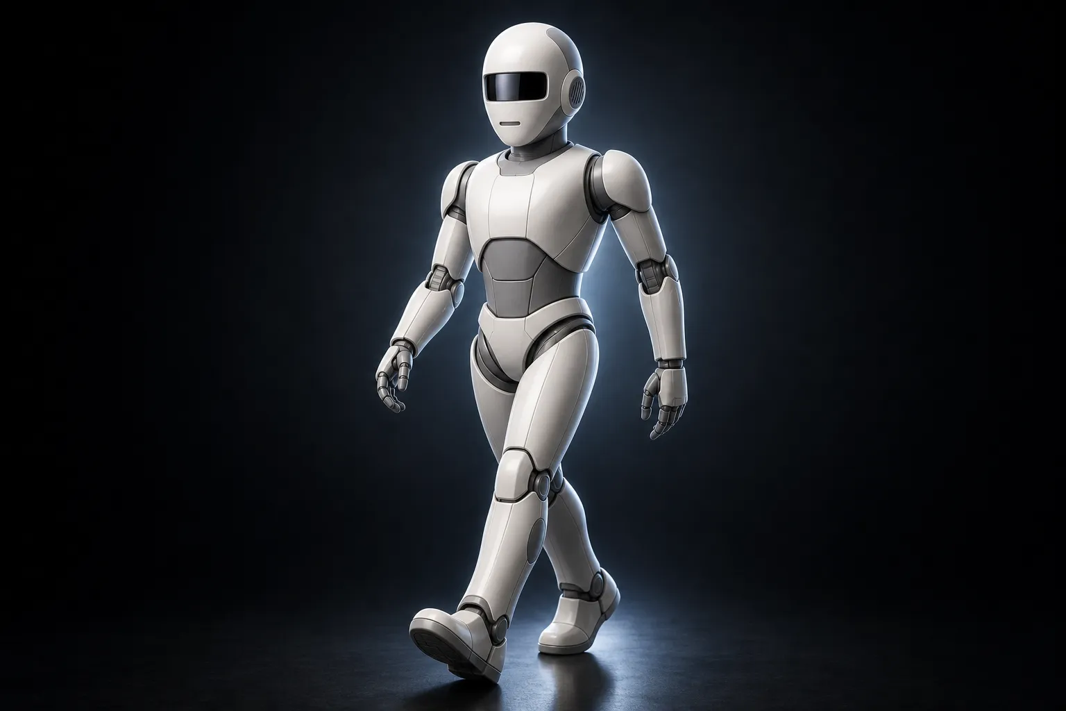
◆ PROJECT MILO — HUMANOID PLATFORM

Hello. I am being
assembled in public.

A bipedal, conversational robot built one subsystem at a time — Raspberry Pi 5 for the body, Jetson for the brain, RealSense for the eyes. Head is done. Hands are next. Everything I learn gets logged here, and every file ends up downloadable.

/ SUBSYSTEM STATUS

Head ACTIVE

2026-07-27 : Finally got shell had to get help from designer to create it for me, I added the camera bracket to hold RealSense D435if

50% COMPLETE
Hands ACTIVE

2026-07-20 -- Started Researching different hands for humanoids. 2026-07-25 -- Still In Design Phase, Setting up Fusion Project

10% COMPLETE
Vision SPEC'D

RealSense D435if streaming depth. No tracking loop yet.

5% COMPLETE
Compute SPEC'D

Pi 5 + Jetson split decided. Power budget open.

5% COMPLETE
Speech / LLM R&D

R&D

0% COMPLETE
Locomotion R&D

Bipedal walking. Hardest problem, deliberately last.

5% COMPLETE
Torso / Frame R&D

R&D

0% COMPLETE
Power R&D

R&D

0% COMPLETE

/ ANATOMY

▸ HEAD

Head + Sensor Pod

Finished Design of Shell, added bracket to house the Intel RealSense D435if for RGB + depth, still need to add brackets for mic and speakers.

STATUS ACTIVE

/ DEVLOG

projectmilo.dev

Seven months in, the project gets a home. projectmilo.dev, on Cloudflare.

Naming was less obvious than it looks — there’s a well-known commercial robot called Milo (RoboKind’s autism-education humanoid) that owns the search results, so the .dev suffix and the “project” prefix are doing real work.

The site is flat static HTML, no build step, dropped straight into Cloudflare Pages. Dark depth-map visual system: a live canvas point cloud rendering Milo’s proportions in roughly 2,800 particles, coloured on a depth ramp from indigo at distance through cyan and amber to hot orange up close, with mouse parallax and a sensor sweep line running down the figure. The hero sets MILO enormous with the same gradient through the letterforms.

Status board covers seven subsystems. The stat rail ends on “0 steps taken” — which is honest, and it stays there until it isn’t true.

Backdating the log to day zero. Turns out that’s 30 December 2025, not 1 January 2026. Two days earlier than I thought, which is a fitting way to discover you’ve been at something longer than you remember.

NEXT → Backfill every entry above and keep this thing current.

Five cuts that make a machined hand printable

Printed the index finger at 61% and learned what everyone learns: a hand designed for machined tolerances does not survive FDM at 61% scale. The fork-and-tab joints bind, bottom out, and won’t seat.

Validated the fix on the Finger_1 coupon. Five operations plus one rule:

  1. Scale to 61% natively in SolidWorks. Not in the slicer. Export the STL and print at 100% — this keeps parametric control and stops the slicer silently scaling tolerances that shouldn’t scale.
  2. Widen the fork slot ~0.25 mm per side into a funnel mouth so the tab self-centres on the way in.
  3. Chamfer or dome the tab lead-in edges.
  4. Slot depth relief so the tab tip doesn’t bottom out before the joint seats.
  5. Shoulder relief so the fork rings seat fully forward.

Then bores: leave them at ~3.05 mm and drill through the assembled joint to fit the 3 mm steel pins. Drilling through assembly trues the alignment in a way no amount of modelling does.

The other outcome — the finger caps are deleted from the BOM. They split along layer seams under hoop stress every time. Retention has to live in the joint geometry itself, not in a separate retaining part. That’s a real design principle, not a workaround.

Sourced precision 3 × 12 mm 18-8 stainless dowel pins, slip fit, 50-pack, as the production pin.

Also confirmed the PTFE Bowden tube trick from the Yeah Hand design solves tendon channel friction, which was going to be the next problem.

NEXT → Apply the same surgery to fingers 2 through 4.

A real parametric skull, and the camera finally fits

Two head tracks converged this week.

The mesh pipeline. Built a depth-map recess detection pass — gaussian baseline subtraction, contour extraction via skimage, Shapely polygon extrusion — that cuts the sculpt’s own mouth and ear slot geometry through to hollow. No invented geometry, no resizing. Took several rounds to get past mask isolation bugs and STL round-trip manifold failures (fixed with manifold3d’s native merge()). Back cover was oversized; measured the head silhouette at each Z height and resized the clamshell opening from 108×150 to 96×96 centred at z=134, verified 5 mm rim clearance.

The commissioned skull. Inderjit delivered the SolidWorks parametric head. I initially misread a binary scan of the .SLDPRT files as dumb imported solids — wrong. The FeatureManager trees show real history: reference surfaces → Scale → sketches and 3D sketches → Surface-Lofts → Trim → Knit → Thicken → Boss-Extrude → Cut-Extrude → Fillets. 123 features on the Skull alone.

Verified via MCP that it’s printable: Skull ~3.7 mm walls, Faceplate ~2.96 mm, Rear Panel ~2.82 mm.

Then into Fusion for integration. Positioned the RealSense D435if behind the faceplate visor, moved 11 mm back for clearance. Built a native camera bracket with 2× M3 holes at ±22.5 mm — 45 mm spacing, matching the real camera’s back holes exactly — plus corner screws and a USB-C cable slot. Fixed a duplicate MirrorEar occurrence problem so all four ear components sit linked and symmetric.

One thing abandoned deliberately: shrinking the faceplate mouth from a perforated grille to a clean 28×8 mm slot. A base-feature temp-BRep operation deleted the whole faceplate body mid-attempt. Recovered by closing without saving. The existing grille is fine and not worth the risk.

Camera spec locked for anyone building along: the D435if’s M3 back holes are only 2.5-3 mm deep — use M3×5 or M3×6, nothing longer. And the 750 nm IR-pass filter means the visor acrylic should be IR-pass, so it can be dark or opaque to visible light.

NEXT → Print the skull and check the RealSense clearance in the real world.

ORCA hand as the reference, Wuji as the north star

Found the ORCA hand from ETH Zürich’s Soft Robotics Lab — open source, 17 DoF, tendon-driven, 16 finger actuators plus a wrist. STEP assembly and Bambu 3MF print profiles are public. That becomes the reference design.

Further out, the Wuji Hand 2 — 20 DoF direct drive, tactile sensing, force control, full URDF and SDK — is the capability benchmark. Not buying one: it’s 180 mm against my 140 mm target and priced like the research tool it is. Its DoF layout and joint ranges are freely documented, which is the part I actually need.

Sourcing worked out:

  • 32× Dynamixel XC330-T288-T (11.1 V TTL) + 2× XC430-T240BB-T. The 11.1 V T288 beats the 5 V M288 on power distribution across a 16-servo tendon chain. Quote request drafted to robotis.us.
  • I already own 7× Feetech STS3215 from a prior LeRobot build — enough for a single-finger mechanical eval before committing to the Dynamixel order.
  • Wrist: Feetech HL-3950, 50 kg·cm at 12 V, identical envelope to the STS3215.
  • Power: one supply per hand, firmware current limits inside the U2D2 Power Hub’s 10 A rating, two U2D2s (one per arm).

Sensing plan: FlexiTac V2 FPC for tactile — open source, ~$2.50 a piece, 32×12 at 2 mm pitch, Isaac Sim support. For joint sensing, arXiv 2605.01434 is an open replacement for ORCA Touch’s closed module: 16 joint sensor modules plus 4-channel tactile on a Teensy 4.1 into ROS 2.

Version-gate holds. Nothing expensive gets ordered until one finger moves.

NEXT → Print and test a single finger on servos I already own.

Repairing a shell that arrived in thirteen pieces

The Coav-R surface body came out of the Meshy pipeline fractured — 13 separate bodies, 85 free edges, 23 open loops. Booleans on it failed instantly.

Repair pipeline that eventually worked:

  1. Remove 12 orphaned shard bodies with RemoveFeatures — direct deleteMe() cascades and takes the parent timeline feature with it
  2. Patch three of four holes with patchFeatures
  3. Fill the stubborn 26-edge non-planar hole with a TemporaryBRepManager triangle fan built from a centroid walk
  4. Stitch at escalating tolerance up to 1.3 mm to close a chord-deviation gap

Result: one watertight solid, 19 faces, 0 open edges. Two ×1.0 mm through-holes drilled after fixing a sketch plane normal mismatch that had been silently killing the extrudes.

Separately, measured the part properly and found the wall thickness is a dead consistent 1.70 mm (p5-p95: 1.68-1.71). Which means it’s a single offset surface trimmed to a silhouette — so the honest fix for the mirror part isn’t repair at all, it’s a parametric trace: outline DXF, 16 section curves, boundary surface, thicken 1.70 mm.

Fusion MCP hazards logged: every script runs as one transaction and any exception rolls back all geometry in it, so risky operations go in their own call. Body names get reassigned after booleans — always re-query immediately before use. And is doesn’t work on BRep proxies; compare .name or .entityToken.

NEXT → Rebuild the mirror part parametrically instead of repairing it too.

12,196 faces down to 14

Spent a session proving something I suspected: you cannot loft your way back to an organic sculpt. Ran the full experiment — 14 mesh-extracted cross sections, fitted splines, centreline guides, pairwise bisection testing. It does not converge. Structurally infeasible, not a skill problem.

Two things that do work:

Convert Mesh for exact-match geometry. Fusion’s built-in mesh-to-BRep gives a solid in the timeline that matches the mesh precisely, at the cost of face count.

Measure and rebuild when you want something clean. Pulled the functional dimensions off the finger link mesh — 45.8 mm length, 16.5 × 16 mm joint width, 3.9 mm pin bore — then built it from scratch with 10 user parameters: disc extrude, tapered beam loft, pin bore, tendon channels, tip fillet.

12,196 faces → 14. Fully parametric.

Also produced a smooth wrist bracket the long way: voxel remesh at 0.5 mm pitch, Taubin smoothing, topology-preserving decimation, QuadriFlow quad remesh built from source. Final output 5,747 faces, 97.9% quads, zero boundary or non-manifold edges, ready for T-Spline conversion. Mean deviation 0.45 mm.

The pattern that comes out of all of it: smooth shell from conversion, parametric re-cuts for every functional interface. Bores, mounting flats and servo pockets never come from the mesh.

NEXT → Repair the surface bodies that came out of the mesh pipeline broken.

A hand at 61% scale

Jumping the roadmap. Found a genuinely articulated tendon-driven hand on GrabCAD (Ozcan Ozaltin design, Turkish feature names) — real pin joints, Cut-Sweep tendon channels running tip to base, tendon anchor bosses. Not a display prop.

Pack-and-Go’d into a new project with English names: Palm, Finger_1 through Finger_4, Connecting_Pin, Finger_Cap, Milo_Hand_Assembly.

Decisions locked:

  • Target hand size 140 mm — a 61% scale factor off the original ~230 mm
  • 3 mm steel rod pins cut to ~12 mm
  • Tendon-driven with servos in the forearm, same approach as Optimus Gen 3
  • Start at 4-5 DoF and iterate up if grip proves insufficient
  • Left hand is a mirror. Build one.

Also bought 11× OVM7692-RYAA image sensors for $61 — the correct substitution part for DIGIT Flex rev. 2021-2 tactile sensors. Roadmap for touch is FSR fingertips first, then one DIGIT on the thumb, then more, with the TACTO simulator for RL training.

Index finger STLs exported. 8 parts. Printing next.

NEXT → Print the index finger and find out what breaks.

Does Milo need a face at all?

Evaluated a 16:1 printed planetary gearbox for NEMA17 steppers and rejected it for joints. Steppers are heavy, have no position feedback, and lose steps under load. They stay on the list only for a neck pan joint, a camera turntable, or a dynamometer rig to characterise other actuators.

The bigger question that opened up: with a Jetson, a RealSense and a Pi 5 all in hand, the division of labour is obvious — Jetson runs perception, Pi 5 runs motion, they talk over ROS 2 Jazzy. Core behaviour is “detect person, turn to face them.”

Which led somewhere I didn’t expect. If the neck turns to face you and an LED signals attention, does Milo need eyes and a mouth at all? A faceless sensor pod is simpler, cheaper, and arguably more honest about what it is.

Not resolved. Resolved instead by design: the faceplate becomes a swappable panel. Expressive face and minimal sensor pod both bolt to the same skull. The animatronic eye work isn’t wasted, it’s just optional.

NEXT → Commission a proper parametric skull instead of hand-sculpting one.

The eye mechanism, modeled live in Fusion

Back to requirement two. Designed the full biomechanical eye — moves in all directions, blinks, tendon-driven.

Architecture is the one professional animatronics uses: a trackball sphere as the eyeball, fishing line as tendons, servos pulling in opposing pairs. Five layers: upper eyelid, iris gear ring, sclera dome, servo bracket and socket, lower eyelid.

Built it live in Fusion 360 through the MCP connector:

  • 50 mm eyeball, revolved from a semicircle profile around the Y axis
  • Socket cup at 55% wrap with 0.3 mm clearance
  • Wire anchor posts at four equator positions
  • 80 × 80 mm rod frame with servo mount tabs and corner rod holes
  • Upper and lower curved eyelid panels, arc profile extruded symmetrically 50 mm

Also wrote robot_eye.py — the Pi 5 controller. Five MG90S servos, HC-SR04 and PIR for presence, opposing tendon pair logic, smooth movement interpolation, idle wander, alert scan, and a startup sequence.

Fusion API note that cost me time: all dimensions go in centimetres, not millimetres. 25 mm radius is 2.5.

NEXT → Split the assembly into components and export STLs.

Sim-to-real pipeline closed end to end

The Berkeley Humanoid Lite platform becomes Milo’s skeleton. Trained a custom biped locomotion policy — 6000 iterations — exported it to ONNX, loaded it in MuJoCo, and drove it with an Xbox controller.

The whole thing hinged on one line. The ONNX export must use input_names=["obs"], because rl_controller.py looks for "obs" first and only falls back to "onnx::Gemm_0". Wrong input name, silent failure.

Two other patches play.py needed against newer IsaacLab and rsl_rl versions: wrap the obs_normalizer AttributeError in try/except, and handle the changed return signature from env.get_observations().

And the flag that saves everything on a Blackwell GPU: --rendering_mode performance prevents shader compiler crashes — for play.py and train.py both, not just headless runs.

Trained policy → ONNX → physics sim → gamepad. That’s the path to hardware, and it works.

NEXT → Train the full 22-DoF humanoid, not just the biped.

milo-ai-bot — clean 24.04 and a real toolchain

The 22.04 install had persistent i915 GSC firmware errors from the Arrow Lake iGPU that no amount of kernel parameter tuning fixed. Clean install of Ubuntu 24.04 on a newer kernel resolves them natively — worth knowing that sometimes the answer is a newer kernel and not a workaround.

The box gets named milo-ai-bot. Which is also the moment the project gets named, because by now it’s clearly not just a head anymore.

What’s on it:

  • Isaac Sim 5.1 built from source with GCC 11 at /mnt/storage/isaacsim (system GCC 13 stays; Isaac gets CC=gcc-11 CXX=g++-11)
  • Isaac Lab at /mnt/storage/IsaacLab
  • ROS 2 Jazzy, full robotics stack
  • FreeCAD-daily with the RobotCAD workbench for URDF export
  • Second NVMe formatted as /mnt/storage, 916 GB, workspace at /mnt/storage/milo_ws

GRUB gets iommu=off pcie_aspm=off, CPU governor pinned to performance via a systemd service, SSH key auth configured, xrdp with XFCE as the GUI fallback. Workflow is SSH-first from here on.

NEXT → Train a policy on the Berkeley Humanoid Lite platform.

Isaac Sim 5.1.0 launches

Clean startup in about 9 seconds. ROS 2 Humble bridge loads. Most of the warning spam is deprecation notices — the old omni.isaac.* module names redirecting to isaacsim.* — plus harmless MESA complaints about the Intel iGPU that isn’t doing the work anyway.

Two real findings worth keeping:

  • CPU governor was sitting on powersave. Fixed with cpupower frequency-set -g performance.
  • IOMMU enabled in BIOS costs simulation performance and I have no VM passthrough use case, so it goes off.

Pipeline for the build gets drawn out here for the first time and it’s the one still in use: CAD → URDF → ROS 2 → Isaac Sim → train → export → real hardware.

NEXT → Get a robot description into the simulator instead of an empty stage.

Building the machine that trains the robot

Scope creep, formally. To train locomotion policies instead of hand-tuning servo curves forever, I need a box that runs NVIDIA Isaac Sim without complaint.

Spec: Intel Core Ultra 9 285K, ASUS ROG STRIX Z890-A, RTX 5080 16 GB, 64 GB DDR5, 2× Samsung 990 EVO Plus 1 TB NVMe.

Then two solid days of NVIDIA driver warfare. The proprietary driver refuses to boot. Recovery mode, purge, reinstall, repeat. The fix is the open kernel module variantnvidia-driver-590-server-open — where the proprietary build failed outright.

Final config that works: driver 590.48.01, CUDA 13.1, prime-select on-demand, Apple Studio Display driven off the Intel iGPU over Thunderbolt. Result is the RTX 5080 sitting at 15 MiB used out of 16,303 MiB at idle — effectively the entire GPU reserved for compute while the desktop runs on integrated graphics.

Lesson filed: when the proprietary driver fights you, try -server-open before you try anything clever.

NEXT → Get Isaac Sim to launch without crashing.

Camera locked — Intel RealSense D435if

Presence detection graduates from “PIR sensor sees warm thing move” to real depth perception. Picked the Intel RealSense D435if.

Why this one:

  • 0.3 m to 3 m ideal range, 28 cm minimum — right for someone standing in front of it in a room.
  • 87° × 58° depth FOV, up to 1280×720 at 90 fps. Depth accuracy under 2% at 2 m.
  • 1920×1080 RGB at 30 fps for faces.
  • Built-in IMU — the head knows its own orientation.
  • IR-pass filter, so it sees in the dark.
  • Global shutter on the depth sensors, metal housing, industrial grade.

Physical constraints that go straight into the CAD file: 90 × 25.8 × 25 mm, USB-C 3.1 Gen 1, one 1/4-20 UNC and two M3 mounting points.

The IR-pass filter has a consequence I don’t appreciate until much later — any visor in front of this camera needs to be IR-transmissive, which means it can be dark or opaque to visible light and still work. That’s a free aesthetic win.

NEXT → Design a head that this thing actually fits inside.

Fiberglass cage, latex skin, and printing the negative

Expanding the skin plan into a full build order: sculpt the positive, pull a two-part silicone mold with a rigid mother mold, lay up a fiberglass cage as the structural underskull, then cast the flexible skin over it.

Side quest that turns out to be more useful — 3D printing vacuum-form molds. For eye shells, teeth and clear eye covers this is faster and cheaper than anything else. Rules that came out of it:

RuleReason
2-3° draft anglePart actually releases
1-2 mm vent holes at detail bottomsAir has to escape
Thick wallsWon’t collapse under vacuum
PETG or ABS, not PLAPLA softens under the heated sheet
Sand the surfaceEvery layer line transfers

Eye shells and clear covers get vacuum-formed. Skull sections stay printed — too complex a shape to be worth it.

NEXT → Vacuum-form a test eye shell off a printed mold.

What goes over the mechanism

Getting ahead of myself and researching skin before the skull exists.

Three tiers, cheapest first:

  • Stretch fabric over the printed structure. Forgiving, hides print imperfections, good enough to prove the mechanisms move.
  • Cast silicone over a sculpted master — clay up the features, mold it, cast a thin skin that slips over the mechanics. Ecoflex 00-30 and Dragon Skin are the candidates because they’re soft enough to transfer jaw and eye movement through the skin instead of fighting it.
  • Direct-applied silicone, which needs practice I don’t have yet.

Practical note that matters for CAD later: the skull has to be designed with 2-4 mm of clearance for skin thickness, plus anchor points and seam locations planned in — back of head, under the chin, hairline.

Plaster cloth works as a mother mold but not as the detail layer. It needs a brush-on silicone or latex inner layer first or the weave texture prints straight through onto the skin.

NEXT → Decide between a rigid printed face and a cast silicone skin.

First light — 33 FPS and a pair of eyes that follow you

Requirement four gets answered the same week it gets written.

Jetson flashed with JetPack 6.2, CUDA and PyTorch installed, YOLO running person and face detection at 33 FPS off a single USB camera. A Pico handles the servo side over serial, and the tracker script feeds detection centroids into eye position.

The eyes track a face across the room. Crude, jittery, range of motion clearly wrong — the eyelids never open fully and the eyes hit their stops early — but the loop is closed: camera sees person, servos move, person sees the robot look back.

Known problems logged for later: single camera means a narrow field of view, and the eyelid limits are being clamped somewhere in the trim logic.

NEXT → Print a second camera eye so there are two of them and the FOV widens.

Five requirements and nothing else

Day zero. The whole project starts as five lines written down in one sitting:

  1. Must be able to listen and respond.
  2. Mouth movement and eyes.
  3. Runs on a Pi 5 or similar.
  4. It has to know if someone is in front of it.
  5. Must be 3D printed.

That’s it. No name yet, no body, no idea that this ends up as an 800 mm humanoid with a tendon-driven hand. Just a head that notices you walked into the room.

First architecture sketch is deliberately boring: Pi 5 as the brain, PCA9685 driving a handful of MG90S servos for eye pan/tilt, eyelids and jaw, a PIR or HC-SR04 for presence, USB mic in and a small amplified speaker out. Speech stack penciled in as Vosk or Whisper for STT and Piper for TTS so the thing can run offline if it has to.

Estimated BOM at this point: about $200-250. That number does not survive contact with reality.

NEXT → Get a camera looking at a face and prove presence detection is real.

/ ROADMAP

P0 · IN PROGRESS

Head + sensing

Shell designed, still need to wrap up mounting brackets

P1 · IN PROGRESS

Arms + hands

Tendon-driven hands

P2 · QUEUED

Perception loop

Track a person, follow with the neck, no jitter.

P3 · QUEUED

Voice + conversation

STT, LLM, TTS on the Jetson. Latency under a second.

P4 · QUEUED

Torso + power

Frame, compute bay, battery and rail isolation.

P5 · QUEUED

Legs + walking

Bipedal balance, then flat-floor walking. The big one.

/ BILL OF MATERIALS

Raspberry Pi 5 (8GB)
body controller
IN HAND
NVIDIA Jetson
perception + LLM
IN HAND
Intel RealSense D435if
RGB + depth vision
IN HAND
Filament + hardware
everything else
ONGOING

/ CHANGELOG

  • v0.4 Depth stream running on Jetson
  • v0.3 Compute architecture locked (Pi 5 + Jetson)
  • v0.2 Head assembly complete
  • v0.1 Scope defined, parts ordered

/ ABOUT

Milo is a humanoid robot I'm building from scratch, and this is the lab notebook. Twenty-plus years as a software engineer means I can make almost anything think. It does not mean I know what a moment arm is. Closing that gap is most of the project.

Almost every part gets manufactured at home — printed on a Bambu Lab H2C, milled on a Makera Air. The constraint is deliberate: keep this cheap enough that anyone with the same two machines can follow along and build their own. Some of what I need doesn't exist yet, so part of the work is building the tools that build Milo.

Everything gets documented — the decisions, the part numbers, the print that warped at hour nine. Every file ends up downloadable. This is going to take a while, and that's fine. Let's get started.